Diamond Micro Wire Saw Instructions
INSTRUCTIONS
General Description:
DIAMOND Micro WIRE SAW
There is no practical way of forming an .008" wire into a continuous loop for rock cutting purposes. A knot cannot be used and a weld of no extra diameter is too weak to provide proper tension. Moreover, a continuous loop will not permit internal cuts to be made in a design.
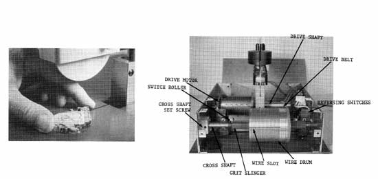
The Gryphon Micro Wire Saw therefore uses a long length of wire which repeatedly reverses direction as it comes to each end. In order for the wire to remain in a constant position on the cutting platform, it is held on a threaded drum which in turn rotates on a screw of the same pitch. One turn~s looped up over a wire pulley which is counter--weighted to provide tension. As much as 50 feet of wire (and as little as 3 feet) may be held on the drum. The height of the loop is adjustable so that perfect squareness can be maintained.
The drum is belt driven from a permanent magnet motor which is reversible in direction by polarity change. Two adjustable roller switches sense the position of the drum at each end of the wire travel. These switches, in turn, either activate or release a relay which changes the polarity of the motor. An electronic speed control is combined with the on-off switch.
A 2 ampere fuse protects the electrical components. Proper grounding of the 3-wire plug is provided for your protection.
Of utmost importance to you is proper consideration of the micro wire, wire, which will promptly get tangled unless these precautions are followed. (Remember: over 50 turns of the wire are wound tightly around the wire drum and must stay in their exact position.) Once hooked up, the wire should be under tension at all times. The weight provides this tension as long as it is in place, and it may remain so indefinitely.
Before unhooking the wire for any reason, the front panel should be removed and the rubber pad wedged securely between the drum and the bottom of the machine to secure the final turns of wire. Following this, the weight can be safely removed.
The machine may be carried with the weight in place if handled gently. For any extensive transporting, it is best to unhook the wire from the drum, tape the end to the inside of the machine and remove the arm assembly.
If the wire becomes tangled, it can usually still be saved. (See sheet on changing wires.)
A safety Shut-off Switch immediately shuts off the power in case of a wire break. This greatly reduces wire tangling and loss and makes re-threading much easier. This switch is directly under, and is triggered by the knob on the bottom of the Weight pin.
Note: This switch remains off after being activated and must be pushed again to unlatch it and restore power to the machine.
General Notes
You are embarking on a completely new method of cutting minerals. While it requires some degree of patience, it can also be very rewarding as you are limited by only your imagination in creating unique pieces that are impossible by any other means.
You will need a small brush (furnished), a wiping pad, and some lubricant. Mineral oil, or even water may be used. Do not use paint thinner, kerosene or any other flammable solvents.
Your pattern may be glued to your stone with white glue and it is a good practice to coat over the pattern after it is in place with the same glue to prevent the lubricant from soaking into the pattern. If water is used as a lubricant, epoxy can be used instead of glue in the same manner.
After cutting, the glue and pattern can easily be removed with soaking in warm water.
The general assumption that increased speed and/or pressure will cut faster does not apply with this machine. Our extensive testing shows that if the wire is traveling too fast, the diamonds just slip past the material rather than cut it, and in addition wire breaks can result. Set the speed control so the wire reverses direction about every 20 seconds to begin with. As you become familiar with the machine, you may wish to vary this slightly as different materials have different best cutting speeds, but not to a critical degree.
Become familiar with the cutting action of this saw before attempting complicated designs. During half of the cutting, the wire blade will be moving downward and tends to hold the slab to the work table. The other times it moves up and tends to lift the slab. Pressure must be applied to the work to overcome this lifting tendency which will vary with different materials. This change in direction will be accompanied by a clicking sound. You may stop cutting at any time merely by returning the speed control to its off position. Your work may be left in place until you wish to begin again.
Note: Whenever the machine is started, the direction of the wire will be down, no matter at what part of the cycle it was turned off.
It is imperative that the material being cut is maintained flat so that the wire passes straight through it without binding. Care should be used not to rock the stone sidewise. In cutting, it is only necessary to feed your pattern to the cutting wire and follow the selected outline.
Use the small brush to apply only enough lubricant to the cutting area so that the wire is in contact with the lubricant at all times to flush away the particles of material being cut. You will find that as the wire travels downward the sludge will build up on the surface of your pattern, and can be removed by a brush and replaced with fresh lubricant. Periodic wiping the brush on a rag will aid in keeping fresh clean lubricant in service. You should plan exactly how and where to begin and end your cut. Normally, you will start and end at the same place after cutting the full pattern. The very first fraction of an inch of cutting is quite slow. Once the wire is fully in to the cut, normal speed will begin.
As you cut, continue to orient your work so the cutting pressure is straight back or straight forward and never to the side. It is a good practice to use both push and pull cutting as this helps gain the maximum service from the wire and it is also more restful to the fingers.
For inside cuts, it is first necessary to drill a hole in the slab. It may either be large enough so the slug will pass through it or if desired just large enough for the wire. In the latter case, the slug end of the wire is cut off and a new slug applied after threading the wire through the drilled hole. (The slugs are "split shot", a very common fisherman's item and are available at hardware and sporting goods stores.)
The proper cutting force is provided for by the size of the weight which was carefully determined by our tests. When you are cutting, use only enough pressure to move the wire about 1/8" to 1/4" from vertical. Even less will give good results on some materials and the less pressure used, the longer the wire will hold up. (Never attempt to cut from the side, but always forward or back.)
Sometimes, when cutting well into a piece of material, it becomes difficult to know if the cutting wire is centered in the slot. One way to check yourself on this is to stop the machine, let up on the cutting pressure and let ,the workpiece float slightly until the wire centers itself.
Another technique is to make a very simple guide. Straighten out a standard paper clip and tape it to the front of the pulley cover so that it lines up with the micro wire. It can be up fairly high so it doesn't interfere with following your pattern. This guide will let you know if you are getting out of line and prevent cutting into the table itself. It can also be used as a guide for the amount of pressure you are using.
We wish to emphasize the importance of cleaning the wire and wire drum. In many cases where a slow down in cutting speed occurs, the cause will be an accumulation of sludge on the wire and drum. This sludge barrier prevents the diamonds from reaching the material being cut.
INSTRUCTIONS
General Description:
DIAMOND Micro WIRE SAW
There is no practical way of forming an .008" wire into a continuous loop for rock cutting purposes. A knot cannot be used and a weld of no extra diameter is too weak to provide proper tension. Moreover, a continuous loop will not permit internal cuts to be made in a design.
The Gryphon Micro Wire Saw therefore uses a long length of wire which repeatedly reverses direction as it comes to each end. In order for the wire to remain in a constant position on the cutting platform, it is held on a threaded drum which in turn rotates on a screw of the same pitch. One turn~s looped up over a wire pulley which is counter--weighted to provide tension. As much as 50 feet of wire (and as little as 3 feet) may be held on the drum. The height of the loop is adjustable so that perfect squareness can be maintained.
The drum is belt driven from a permanent magnet motor which is reversible in direction by polarity change. Two adjustable roller switches sense the position of the drum at each end of the wire travel. These switches, in turn, either activate or release a relay which changes the polarity of the motor. An electronic speed control is combined with the on-off switch.
A 2 ampere fuse protects the electrical components. Proper grounding of the 3-wire plug is provided for your protection.
Of utmost importance to you is proper consideration of the micro wire, wire, which will promptly get tangled unless these precautions are followed. (Remember: over 50 turns of the wire are wound tightly around the wire drum and must stay in their exact position.) Once hooked up, the wire should be under tension at all times. The weight provides this tension as long as it is in place, and it may remain so indefinitely.
Before unhooking the wire for any reason, the front panel should be removed and the rubber pad wedged securely between the drum and the bottom of the machine to secure the final turns of wire. Following this, the weight can be safely removed.
The machine may be carried with the weight in place if handled gently. For any extensive transporting, it is best to unhook the wire from the drum, tape the end to the inside of the machine and remove the arm assembly.
If the wire becomes tangled, it can usually still be saved. (See sheet on changing wires.)
A safety Shut-off Switch immediately shuts off the power in case of a wire break. This greatly reduces wire tangling and loss and makes re-threading much easier. This switch is directly under, and is triggered by the knob on the bottom of the Weight pin.
Note: This switch remains off after being activated and must be pushed again to unlatch it and restore power to the machine.
General Notes
You are embarking on a completely new method of cutting minerals. While it requires some degree of patience, it can also be very rewarding as you are limited by only your imagination in creating unique pieces that are impossible by any other means.
You will need a small brush (furnished), a wiping pad, and some lubricant. Mineral oil, or even water may be used. Do not use paint thinner, kerosene or any other flammable solvents.
Your pattern may be glued to your stone with white glue and it is a good practice to coat over the pattern after it is in place with the same glue to prevent the lubricant from soaking into the pattern. If water is used as a lubricant, epoxy can be used instead of glue in the same manner.
After cutting, the glue and pattern can easily be removed with soaking in warm water.
The general assumption that increased speed and/or pressure will cut faster does not apply with this machine. Our extensive testing shows that if the wire is traveling too fast, the diamonds just slip past the material rather than cut it, and in addition wire breaks can result. Set the speed control so the wire reverses direction about every 20 seconds to begin with. As you become familiar with the machine, you may wish to vary this slightly as different materials have different best cutting speeds, but not to a critical degree.
Become familiar with the cutting action of this saw before attempting complicated designs. During half of the cutting, the wire blade will be moving downward and tends to hold the slab to the work table. The other times it moves up and tends to lift the slab. Pressure must be applied to the work to overcome this lifting tendency which will vary with different materials. This change in direction will be accompanied by a clicking sound. You may stop cutting at any time merely by returning the speed control to its off position. Your work may be left in place until you wish to begin again.
Note: Whenever the machine is started, the direction of the wire will be down, no matter at what part of the cycle it was turned off.
It is imperative that the material being cut is maintained flat so that the wire passes straight through it without binding. Care should be used not to rock the stone sidewise. In cutting, it is only necessary to feed your pattern to the cutting wire and follow the selected outline.
Use the small brush to apply only enough lubricant to the cutting area so that the wire is in contact with the lubricant at all times to flush away the particles of material being cut. You will find that as the wire travels downward the sludge will build up on the surface of your pattern, and can be removed by a brush and replaced with fresh lubricant. Periodic wiping the brush on a rag will aid in keeping fresh clean lubricant in service. You should plan exactly how and where to begin and end your cut. Normally, you will start and end at the same place after cutting the full pattern. The very first fraction of an inch of cutting is quite slow. Once the wire is fully in to the cut, normal speed will begin.
As you cut, continue to orient your work so the cutting pressure is straight back or straight forward and never to the side. It is a good practice to use both push and pull cutting as this helps gain the maximum service from the wire and it is also more restful to the fingers.
For inside cuts, it is first necessary to drill a hole in the slab. It may either be large enough so the slug will pass through it or if desired just large enough for the wire. In the latter case, the slug end of the wire is cut off and a new slug applied after threading the wire through the drilled hole. (The slugs are "split shot", a very common fisherman's item and are available at hardware and sporting goods stores.)
The proper cutting force is provided for by the size of the weight which was carefully determined by our tests. When you are cutting, use only enough pressure to move the wire about 1/8" to 1/4" from vertical. Even less will give good results on some materials and the less pressure used, the longer the wire will hold up. (Never attempt to cut from the side, but always forward or back.)
Sometimes, when cutting well into a piece of material, it becomes difficult to know if the cutting wire is centered in the slot. One way to check yourself on this is to stop the machine, let up on the cutting pressure and let ,the workpiece float slightly until the wire centers itself.
Another technique is to make a very simple guide. Straighten out a standard paper clip and tape it to the front of the pulley cover so that it lines up with the micro wire. It can be up fairly high so it doesn't interfere with following your pattern. This guide will let you know if you are getting out of line and prevent cutting into the table itself. It can also be used as a guide for the amount of pressure you are using.
We wish to emphasize the importance of cleaning the wire and wire drum. In many cases where a slow down in cutting speed occurs, the cause will be an accumulation of sludge on the wire and drum. This sludge barrier prevents the diamonds from reaching the material being cut.
ADJUSTMENTS
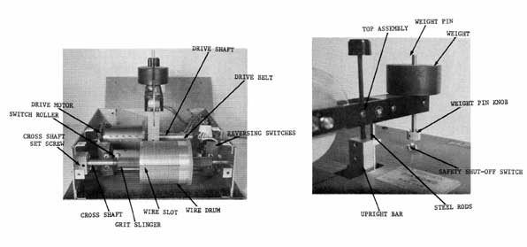
1. Leveling: The Balance Arm Assembly should be kept relatively level. Rotate the Leveling Knob in the direction needed to maintain this position.
2. Reversing Switches: The function of each of these is to cause the Wire Drum to reverse its direction just before reaching the end of the wire. One full loop of wire should always remain on the drum at each end as insurance. Turning either Reversing Switch Knob counter-clockwise will cause the drum to reverse earlier. Adjustment of these switches is explained fully in the section on "Changing the Wire".
3. Weight Pin; A Brass Thumb Screw at the rear of the Balance Arm permits the height of the pin to be adjusted. This is normally required only in respect to changes in the leveling of the Balance Arm or when the Micro Wire is replaced or repaired.
4.Cross Shaft: This is properly adjusted at the factory and should not need attention unless the machine is improperly threaded. For example: If when beginning to thread the Wire onto the Wire Drum, you start in the second groove instead of the first, the wire will not be centered in the Work Panel Slot and will be on a slant. Rather than unthread and start all over, you can make this correction. Leave the Work Panel in place.
a. Loosen the Cross Shaft Set Screw.
b. Engage a screwdriver with the slot in the left end of the Cross Shaft (from outside of the cover).
c. Hold the Wire Drum so it cannot turn and rotate the Cross Shaft clockwise one turn. Now center the wire in the slot by moving the shaft and drum as a unit. Finally secure the shaft using the set screw. Following this; the reversing switches will likely need re-adjustment. Another example: Your Micro Wire breaks and you apply a new anchor slug and loop up the wire and find it off center. This adjustment may again be used by rotating the Cross Shaft in the appropriate direction. Always check that the shaft extends just outside of the right side panel before tightening the set screw.
SERVICING
Cleaning: The Wire Drum and Wire Pulley should be cleaned frequently to prevent a slowdown of cutting due to accumulated sludge. A brush of the stiff bristle type works well and it can be dipped in water and shaken out to help soften the sludge. Following this, an absorbent towel or rag should be used. Before installing a new wire this cleaning should be thorough, and a piece of thin cardboard used to clean out the slots.
The Cross-Shaft should occasionally be cleaned and new grease applied. With the Drum at either end, slip off the opposite grit slinger, wipe off the shaft as well as possible and apply a liberal coating of grease. (Lubriplate is very good). Then repeat with the opposite portion of the shaft.
Wire Breaks: The replacement of wire is covered by a special sheet. However, if a break occurs, it is necessary to apply a new anchor slug to the wire. Our practice is to tie a knot in the wire and clamp the slug just below it.
ASSEMBLY AND HOOK UP
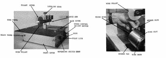
Please: Don't move any controls or knobs until advised to do so. Install the Top Assembly less weight by sliding the two steel rods into the matching holes behind the upright bar at machine center. The wire pulley faces forward. Be sure the rods also are through the lower holes and are fully down. Remove the pulley cover, work panel and front cover. Each is held by 2 brass thumb screws. Remove the tape and plastic shield protecting the Safety Shut-off Switch.
ullout the cardboard pieces that support the motor for shipping. DO NOT. move the Wire Drum. It must remain in its present position for proper alignment. A full length of Micro Wire is threaded on the drum ready for hook up. Remove the tape at the right hand side of the drum. This frees the end of the Micro Wire. Peel back the strip of tape at the left side, leaving the lower portion in place to prevent the wire from getting loose. (The rubber pad under the drum is also for this purpose.)
Pass the end of the Micro Wire up over the Wire Pulley (front to back) and slip the wire into the wire slot in the drum marked with red with the slug inside the drum to anchor the wire. You will note that every groove in the drum has a loop of wire excepting the few at the far left end. The wire you are hooking up must go in the empty groove next to the last full one. Lift up slightly on the Wire Pulley to keep the wire taunt during this procedure, and when the wire end is in its proper position, slip the Weight in place over its weight pin. This gives proper tension to the wire. Now remove the tape and pad. Check yourself; rotate the drum by hand by pushing backward on the top about 3/4 of a turn. The end you have just engaged is now in front where you can check it. As you rotate the drum a little more, you should see a single empty groove directly below the pulley. This is correct. If there is no empty groove you have engaged the wire too far to the right. If there are two or more empty grooves, you are too far left. Return the drum to its former position. Hold tension on the pulley, remove the weight and correct your hook up. Replace the weight and double check yourself by again rotating the drum in the same direction a few turns.
Check the level of the balance arm. If the weight end is low, turn the leveling knob right, if high, to the left. Check the weight Pin. The knob at the bottom should clear the switch button by about 1/4 inch. If necessary adjust it by means of the Brass Thumb Screw at the rear of the arm. Replace all covers and plug the power cord into a 3-wire grounding outlet. Turn on your machine. The Speed Control is also an on-off switch. Rotate clockwise until it clicks. The pilot light just in front of the Control should light at this time. If there is no power, the Safety Shut-off Switch is in the "off" position. Depress the switch plunger so it is at its high position.
As you rotate the Speed Control, the wire begins to travel. You will hear a click as the Wire Drum reverses just before the end of the wire is reached. Time the clicks so they occur about each 20 seconds by adjusting the Speed Control. Note this position on the dial, as it is the proper speed setting. Now you are ready to begin cutting.
To remove a full Wire:
Run the machine until the Wire Drum is fully to the right side, then shut off the power. Unplug the power cord and remove the work table, front panel and pulley cover. Rotate the wire drum by hand (top forward) until the end of the wire is reached. If necessary, back off the reversing switch by turning the knob clockwise. Be certain not to force the switch roller back too far and damage it. Insert the rubber pad and remove the weight. Unhook the end of the wire and slip it over the wire pulley. Remove the wire by removing the pad and pulling the wire off the drum. As you do this, ,the drum will rotate and return to the left side' where rethreading will begin. When fully unthreaded, slip the end of the wire out through the slot to the left.
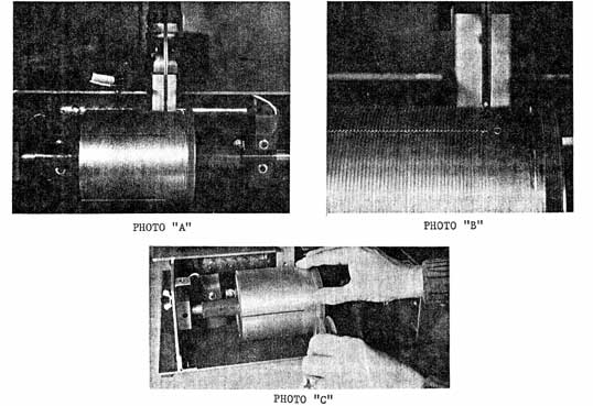
Before installing a new Micro Wire it is important to clean the wire drum and pulley thoroughly. Following this, the proper starting position of the drum must be reset. This is accomplished by manually rotating the drum until it makes contact with the Left Hand reversing switch roller. Now lower the Wire Pulley until it just touches the drum and continue to rotate the drum until the lead thread of the Drum is in exact alignment with the pulley. (During this time you will compress the reversing switch spring about half way.) If necessary, back off the reversing switch by turning the knob clockwise. Caution: When you begin threading, this switch roller must be almost fully compressed. This position is, shown in photo "A". Photo "B" shows a close-up of this relationship and the "0" start mark where you engage the end of the new wire. Photo "c" shows the proper threading procedure. The drum is being rotated forward so the wire threads on from the bottom of the wire drum.
Insert one end of the Micro Wire into the "0" Marked slot with the slug inside the drum. Move the wire to the extreme right position in the slot.
Now rotate the drum by hand with the top of the drum coming forward as the wire is fed onto the drum. Use care to see that each groove is filled with one (and only one) turn of wire. Continue until the other end of the wire is reached. Leaving about 18" of the wire free, force the rubber pad between the bottom of the drum and the base plate to prevent the wire from unwinding from the drum.
Lower the balance arm, until when horizontal, the pulley clears the top of the drum by about 1 inch. Now follow the hook up procedure used in setting up the machine originally, except that from now on, you will be using the most convenient wire slot and ignoring the red marking. After you have completed the hook up and rotated the drum by hand to where you can inspect the position of the wire, you will need to adjust the reversing switch. Rotate the drum one more half turn (push back on the top of the drum).
Rotate the adjusting knob for the right hand reversing switch clock-wise until the roller is clear of the drum. Then counter clock-wise until you hear a very slight click as the switch activates. (You must listen closely as the sound is just a tick.) Thread up is now completed, but it will be wise to double check yourself on the proper setting of both reversing switches.
Move the wire drum by hand away from the right switch roller, then bring it back while listening for the click. At least one full turn of wire should be still threaded. Next, rotate the drum to its full left position and repeat the check with the left reversing switch. Following this, replace all covers and you are ready to cut. If the wire breaks while the machine is running, a number of strands of wire will be loose and may be tangled.
Usually most of the wire can be salvaged by carefully untangling it and winding it off the drum onto a cylindrical form. (Care must be taken to prevent jamming the drum into the micro switch and causing it to break.)
Under these conditions, it is probable that the drum will be out of alignment with the upper roller and the preceding reset procedure must be followed. Occasionally, when a break occurs and the machine is not promptly stopped, a situation can result where the wire cannot be fully removed from the drum because of the right hand reversing switch location.
In this case, when you wish to save the wire, proceed in this manner:
Using your small allen wrench, loosen the set screw that secures the cross shaft (on current models this is located in a block supporting the left end of the shaft). The shaft has a slot in the left end that is accessible from the outside. Using a screwdriver, hold the drum to keep it from turning while rotating the cross shaft clockwise. This will move the drum towards the center of the machine where you can remove the rest of the wire. (if the right end of the the shaft slips out of its recess hole, just slip it back in place.) When you have enough clearance to remove the wire, secure the shaft by means of the set screw. The right end of the shaft should just slightly extend out of the side panel.
If the wire is not worth salvaging, you can avoid this procedure by just cutting it or unthreading it with the drum stationary.
To make inside cuts, you unhook the end of the wire as described in (removing a full wire). Once the wire has been slipped over the Wire Pulley you can remove the slug and thread the wire through the hole in your piece. Install a new slug and complete the hook-up.
CUTTING TECHNIQUES
You are embarking on a completely new method of cutting minerals. While it requires some degree of patience, it can also be very rewarding as you are limited by only your imagination in creating unique pieces that are impossible by any other means.
The general assumption that increased speed and/or pressure will cut faster does not apply with this machine. Our extensive testing shows that if the wire is traveling too fast, the diamonds just slip past the material rather than cut it, and in addition wire breaks can result. Set the speed control so the wire reverses direction about every 20 seconds to begin with. As you become familiar with the machine, you may wish to vary this slightly as different materials have different best cutting speeds, but not to a critical degree. The proper cutting force is provided for by the size of the weight which was carefully determined by our tests. When you are cutting, use only enough pressure to move the wire about 1/8" to 1/4" from vertical. Even less will give good results on some materials and the less pressure used, the longer the wire will hold up. (Never attempt to cut from the side, but always forward or back.)
Sometimes, when cutting well into a piece of material, it becomes difficult to know if the cutting wire is centered in the slot. One way to check yourself on this is to stop the machine, let up on the cutting pressure and let the work-piece float slightly until the wire centers itself.
Another technique is to make a very simple guide. Straighten out a standard paper clip and tape it to the front of the pulley cover so that it lines up with the micro wire. It can be up fairly high so it doesn't interfere with following your pattern. This guide will let you know if you're getting out of line and prevent cutting into the table itself. It can also be used as a guide for the amount of pressure you are using. We wish to emphasize the importance of cleaning the wire and wire drum. In many cases where a slow down in cutting speed occurs, the cause will be an accumulation of sludge on the wire and drum. This sludge barrier prevents the diamonds from reaching the material being cut.
The procedure for cleaning is given in the servicing section: however. there is one additional step that can be very helpful. At times, this sludge can only be removed by softening it. Use a brush or sponge to apply coolant (water or mineral oil) directly to the grooves of the drum. Dip the brush in coolant and apply to the portion of the drum which is accessible. Wipe the surplus off with a soft cloth as described. Do the same with a new position of the drum until the entire drum is clean.
Reference is made in the servicing section about cleaning the Wire Drum under power. This should be avoided. Whenever any panels are to be removed from the machine, it should first be unplugged from the outlet and not reconnected until all panels are again in place. This is a safety rule that is for your protection. Under general notes, corn oil and olive oil are listed as possible coolants to use. We have learned through experience that these have a tendency to become rancid over a period of time and give the machine a disagreeable odor. Please use a light mineral oil or plain water. Water is best for turquoise, how1ite, opal and jade, while mineral oil will be better on other materials.
INSTRUCTIONS
Precision Slicing Attachment for Diamond Micro Wire Saw
Run the machine until the Wire Drum is fully to the right side, then shut off the power. Unplug the power cord and remove the work table, front panel and pulley cover. Rotate the wire drum by hand (top forward) until the end of the wire is reached. If necessary, back off the reversing switch by turning the knob clockwise. Be certain not to force the switch roller back too far and damage it. Insert the rubber pad and remove the weight. Unhook the end of the wire and slip it over the wire pulley. Remove the wire by removing the pad and pulling the wire off the drum. As you do this, ,the drum will rotate and return to the left side' where rethreading will begin. When fully unthreaded, slip the end of the wire out through the slot to the left.
Before installing a new Micro Wire it is important to clean the wire drum and pulley thoroughly. Following this, the proper starting position of the drum must be reset. This is accomplished by manually rotating the drum until it makes contact with the Left Hand reversing switch roller. Now lower the Wire Pulley until it just touches the drum and continue to rotate the drum until the lead thread of the Drum is in exact alignment with the pulley. (During this time you will compress the reversing switch spring about half way.) If necessary, back off the reversing switch by turning the knob clockwise. Caution: When you begin threading, this switch roller must be almost fully compressed. This position is, shown in photo "A". Photo "B" shows a close-up of this relationship and the "0" start mark where you engage the end of the new wire. Photo "c" shows the proper threading procedure. The drum is being rotated forward so the wire threads on from the bottom of the wire drum.
Insert one end of the Micro Wire into the "0" Marked slot with the slug inside the drum. Move the wire to the extreme right position in the slot.
Now rotate the drum by hand with the top of the drum coming forward as the wire is fed onto the drum. Use care to see that each groove is filled with one (and only one) turn of wire. Continue until the other end of the wire is reached. Leaving about 18" of the wire free, force the rubber pad between the bottom of the drum and the base plate to prevent the wire from unwinding from the drum.
Lower the balance arm, until when horizontal, the pulley clears the top of the drum by about 1 inch. Now follow the hook up procedure used in setting up the machine originally, except that from now on, you will be using the most convenient wire slot and ignoring the red marking. After you have completed the hook up and rotated the drum by hand to where you can inspect the position of the wire, you will need to adjust the reversing switch. Rotate the drum one more half turn (push back on the top of the drum).
Rotate the adjusting knob for the right hand reversing switch clock-wise until the roller is clear of the drum. Then counter clock-wise until you hear a very slight click as the switch activates. (You must listen closely as the sound is just a tick.) Thread up is now completed, but it will be wise to double check yourself on the proper setting of both reversing switches.
Move the wire drum by hand away from the right switch roller, then bring it back while listening for the click. At least one full turn of wire should be still threaded. Next, rotate the drum to its full left position and repeat the check with the left reversing switch. Following this, replace all covers and you are ready to cut. If the wire breaks while the machine is running, a number of strands of wire will be loose and may be tangled.
Usually most of the wire can be salvaged by carefully untangling it and winding it off the drum onto a cylindrical form. (Care must be taken to prevent jamming the drum into the micro switch and causing it to break.)
Under these conditions, it is probable that the drum will be out of alignment with the upper roller and the preceding reset procedure must be followed. Occasionally, when a break occurs and the machine is not promptly stopped, a situation can result where the wire cannot be fully removed from the drum because of the right hand reversing switch location.
In this case, when you wish to save the wire, proceed in this manner:
Using your small allen wrench, loosen the set screw that secures the cross shaft (on current models this is located in a block supporting the left end of the shaft). The shaft has a slot in the left end that is accessible from the outside. Using a screwdriver, hold the drum to keep it from turning while rotating the cross shaft clockwise. This will move the drum towards the center of the machine where you can remove the rest of the wire. (if the right end of the the shaft slips out of its recess hole, just slip it back in place.) When you have enough clearance to remove the wire, secure the shaft by means of the set screw. The right end of the shaft should just slightly extend out of the side panel.
If the wire is not worth salvaging, you can avoid this procedure by just cutting it or unthreading it with the drum stationary.
To make inside cuts, you unhook the end of the wire as described in (removing a full wire). Once the wire has been slipped over the Wire Pulley you can remove the slug and thread the wire through the hole in your piece. Install a new slug and complete the hook-up.
CUTTING TECHNIQUES
You are embarking on a completely new method of cutting minerals. While it requires some degree of patience, it can also be very rewarding as you are limited by only your imagination in creating unique pieces that are impossible by any other means.
The general assumption that increased speed and/or pressure will cut faster does not apply with this machine. Our extensive testing shows that if the wire is traveling too fast, the diamonds just slip past the material rather than cut it, and in addition wire breaks can result. Set the speed control so the wire reverses direction about every 20 seconds to begin with. As you become familiar with the machine, you may wish to vary this slightly as different materials have different best cutting speeds, but not to a critical degree. The proper cutting force is provided for by the size of the weight which was carefully determined by our tests. When you are cutting, use only enough pressure to move the wire about 1/8" to 1/4" from vertical. Even less will give good results on some materials and the less pressure used, the longer the wire will hold up. (Never attempt to cut from the side, but always forward or back.)
Sometimes, when cutting well into a piece of material, it becomes difficult to know if the cutting wire is centered in the slot. One way to check yourself on this is to stop the machine, let up on the cutting pressure and let the work-piece float slightly until the wire centers itself.
Another technique is to make a very simple guide. Straighten out a standard paper clip and tape it to the front of the pulley cover so that it lines up with the micro wire. It can be up fairly high so it doesn't interfere with following your pattern. This guide will let you know if you're getting out of line and prevent cutting into the table itself. It can also be used as a guide for the amount of pressure you are using. We wish to emphasize the importance of cleaning the wire and wire drum. In many cases where a slow down in cutting speed occurs, the cause will be an accumulation of sludge on the wire and drum. This sludge barrier prevents the diamonds from reaching the material being cut.
The procedure for cleaning is given in the servicing section: however. there is one additional step that can be very helpful. At times, this sludge can only be removed by softening it. Use a brush or sponge to apply coolant (water or mineral oil) directly to the grooves of the drum. Dip the brush in coolant and apply to the portion of the drum which is accessible. Wipe the surplus off with a soft cloth as described. Do the same with a new position of the drum until the entire drum is clean.
Reference is made in the servicing section about cleaning the Wire Drum under power. This should be avoided. Whenever any panels are to be removed from the machine, it should first be unplugged from the outlet and not reconnected until all panels are again in place. This is a safety rule that is for your protection. Under general notes, corn oil and olive oil are listed as possible coolants to use. We have learned through experience that these have a tendency to become rancid over a period of time and give the machine a disagreeable odor. Please use a light mineral oil or plain water. Water is best for turquoise, how1ite, opal and jade, while mineral oil will be better on other materials.
INSTRUCTIONS
Precision Slicing Attachment for Diamond Micro Wire Saw
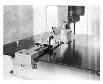
The photo shows the slicing unit properly mounted to the work table of a Micro Wire Saw. A cut through a piece of turquoise is about half completed. Conventional dopping wax is used to hold the stone to one of the three special dops furnished. Two thumb screws make mounting and removal of the dops a simple matter.
The short feed spring is being used, with the spring block positioned for maximum force. This block is designed to provide three different spring tensions depending on the way it is placed. The long feed spring will be used to complete the cut. The springs and block are separate from the unit for simplicity and versatility.
To start a cut, remove the spring and position the slide so the stone is just in front of the wire. By loosening the two lower thumb screws, the unit can be positioned in line with the place you wish to cut. Be sure the unit is squarely against the work table when these screws are tightened. Turn on the wire Saw and set the speed. Begin cutting, using light hand pressure until the wire has seated and then slip in the spring and if needed, the spring block. Apply lubricant and further operation is automatic. Sufficient tension should be used to force the micro wire back at least 1/4 inch and it may be as great as 1/2 inch. With an occasional addition of lubricant, the cut will now be automated except for adding spring tension if required. The long feed spring is used for the final cutting of relatively large or long pieces. At the end of a cut the spring tension should be light to prevent burrs.
If the cut piece is very small or thin, a piece of cardboard may be used to cover the opening in the work table so the piece doesn't fall through. Also on small pieces, a paper towel or cloth may be placed in front of the saw area to contain the piece as it separates. Sufficient lubrication is important, otherwise the wire may bind in the cut. The wire drum serves to act as a reservoir of lubricant and permits fairly long periods without attention. If water is used as a lubricant, the addition of 30 to 50% glycerine will slow the evaporation rate and allow for longer unattended periods.
In starting a cut on a sloping surface, it frequently helps to hold the wire against the stone with your coolant brush to prevent it from slipping. Perfectly flat cuts are produced when the top, bottom and the start of the stone are parallel to the table and the wire. This is true also in cutting a ball in half.
For economy's sake we suggest that the use of this cutting technique be limited to those jobs where the value of the material or piece being cut justify it. The cutting life of a Micro Wire blade is determined largely by the area being cut as well as the type of material.
For slicing large size pieces it may be necessary to raise the height of the balance arm for clearance of the wire pulley. This can be avoided in some cases by positioning the stone low on the dop, allowing it to extend well below the dop if necessary.